Monday, May 19, 2008
Some wing details
A few wing detail pictures appear to be in order.
 First of all my OFPSS (optical flap position sensor system). This gives me repeatability as to where I set the flaps. Cost and weight? Nothing. Why would I want more?
I am somewhat amused by the need for electronics to achieve this. Perhaps some builders like the opportunity to increase the possibility for a fault, spending more money or increasing weight?
 I think this is a normal approach to the installation of the magnetometer, though I took a few attempts before I built it in this obvious way.
 Obtaining a good distance between the transponder and radio antenna can be problematic. The radio aerial is almost under the pilots stick, but the transponder is here, just in front of the rear spar in the gap between the fuselage and wing structure. Should I need access to it I will just have to remove the wing/fuse intersection fairing.
.
Tuesday, October 09, 2007
Trailing edge rivets and general layout.

I have been asked for a few pictures of the trailing edge of the wing to see how they go together. Sorry the pictures are not better.


Thursday, April 19, 2007
Wing / fuselage intersection fairing
 For the wing/fuselage intersection fairing Vans provide you with two parts. A pre-made fiberglass fairing for the front of the wing and a piece of bent ally for the rear. I ran into three problems: i) the intersection between the two parts was quite difficult to manage effectively. ii) the aluminium part was difficult to bend over the top of the wing. iii) it was difficult to terminate it aesthetically at the trailing edge.
I considered building a one piece fairing from scratch and opened my quest for knowledge on Vansairforce.
http://www.vansairforce.com/community/showthread.php?t=17022
In the thread above I was urged to KISS. (Thanks guys!) Here is the result:


The huge advantage is that it is simple, and much lighter than the alternative approaches. I can always return and do something else later, but right now I am happy to be able to move on since I have been stuck on this for nearly 6 weeks.
Sunday, March 25, 2007
Fuel pipe from left tank. (Flop tube side.)
 The path from the left hand tank, if it contains a flop tube, into the fuselage, is not an easy one.
The problem is the F-463 bracket is in the way, the space is narrow, and you have to keep the fuel tube inside the profile of the wing, or at least the fairing. It is possible however, though I had to use bending springs as well as a pipe bender to achieve it. The result will probably make the fuel giddy with the bends it has to go around, but at least this makes sure the stress is minimised and the springiness of the pipe maximised. It is a little untidy, but this is a lesser issue since it will be hidden once the fairing is in place.
As it snakes around the F-463 the pipe is clear of it at all times despite how it looks in the pictures.
Beyond the fitting on the wall of the fuselage, I will continue in the FUSELAGE section of the blog.
The second picture is from underneath.

Wednesday, March 21, 2007
Flap switch for AoA
 Deciding where to place the flap switch, which lets the AoA know the wing configuration, was somewhat difficult. Lots of the candidate positions would be hard to get to once the floor is riveted down, making maintenance difficult.
In the end, I have put it on the bracket on the RHS. The switch will bolt to the little brown bracket sticking up. Its lever hangs down and will get forced back just before the flaps are fully retracted.
If you double click on the picture to make it larger you will just be able to see the bolt holes.

Thursday, March 01, 2007
Flaps - continued...
 The left hand flap is finally working and running through the full range of 44 degrees.
Two points are worth noting. This picture shows the attachment of the drive bearing to the flap. 4 of the rivets attaching the angle to the lower surface are CS4-4. The sticky up heads leave no room for a normal nut so I had to use a metal lock nut. This just fits. I did not think of this solution until I had drilled the CS4-4 out once and tried to set a normal rivet in there. This proved impossible.

I have included this picture so you can see the hole in the floor.
I think the RH flap will be easier and quicker now I have done it before.
Wednesday, February 28, 2007
Important reading if you have not set up your flaps yet!
 I am in the middle of setting up my flaps. The build manual suggests you have between 42 and 44 degrees flap movement on the ground which should give you about 40 in the air under load. See p 8-10. I have been struggling to get more than 35 or 36. Then I noticed the wording on Dwg. EF4-4. (Double click the picture if you want a larger copy.) Here is the conversation I had with VANS.
My question:
When I finished for today I was having a problem getting the full 44 deg flap movement the build book suggests when unloaded. I am probably 10 deg short. All the dimensions/geometry are to plan as far as I can see. However, I have just noticed that at the top LH of Dwg. EF4-4 it sais "Approx 2 3/16th as required". Is this an acknowledgement that this length will have to be adjusted to get the full movement? If I drill a new hole about 3/8th over I would think I will be nearly there. Stresses in the system / motor will increase of course. Thoughts?
VANS response:
Seems curious - the copy of EF4-4 I have shows the dim on the EF-401 as "approx 3". Obviously someone changed it to 2 3/16 for some reason; my guess is that builders said 3" is too long. 2 3/16 is too little, apparently. I'd just move the flaps to see what movement is required at the actuator arm, and drill a new hole accordingly.
I suggest you therefore you drill that hole after you have set up the flap push rods. If you are luckier than I,you had the 3" version of the plan, though I would think that is too long.
I started a thread on VANSAIRFORCE which you may want to review. It has some useful pictures. See http://www.vansairforce.com/community/showthread.php?t=15409
Postscript By adjusting the 2 3/16th dimension to 2 5/8th I have achieved a full 44 deg of movement.
Sunday, February 25, 2007
Setting up the Flaps
 I started to set up the flaps today. The first puzzle was how to get the hinge pin in since one end is blocked by the fuselage, the other by the aileron bracket, and VANS make no comment in the build book that I can find. One very helpful suggestion from a previous builder was to divide the hinge in half and remove some hinge 'ears' from the centre of the hinge. This would clearly work, but somehow to me it seemed a shame to break the continuity of the pin. What I have done is drilled a hole just large enough for the pin to pass through, in the aileron bracket as you can see in the picture. My idea is then to fill the hole with a small c/s bolt with a Nylok. Probably a #4, but I have not looked into that yet. The hinge will then be floating, with neither end secure, but nowhere for it to migrate to. I might well put a small circle of UHM on the fuselage to stop the paint being damaged.
 If anyone can think of a reason why this will not work please let me know.
Thursday, February 15, 2007
Wing tip

Finally I have made it back to the wing tip. With the aileron locked, the tip is lining up nicely. I have reinforced the inside of the tip with ally, so the plate nuts have a firm base to pull against.
Rear spar bolts complete
 The rear attachments are finally drilled to full size. The 5/8" distance is exceeded. The wing incidence is as close as a digital level can measure.
Wednesday, January 31, 2007
Rear Spar
The flaps and ailerons fit well in a trial , so it is time to drill the rear spar attach bolts out to 5/16th. In order to achieve the 5/8th clearance I have had to force both rear spars down somewhat, but all the critical distances have been achieved.
I was delighted by a tool that another British RV builder had fabricated to aid in the drilling of the rear spar. Very ingenious. Needless to say, he was kind enough to lend it to me. Its a clamp and drill guide all in one. Its not easy to use in the cramped space, but that is because of the lack of room.
 In order to achieve the 5/8th clearance I have had to force both rear spars down somewhat, but all the critical distances have been achieved.
I was delighted by a tool that another British RV builder had fabricated to aid in the drilling of the rear spar. Very ingenious. Needless to say, he was kind enough to lend it to me. Its a clamp and drill guide all in one. Its not easy to use in the cramped space, but that is because of the lack of room.
It came with three brass inserts to facilitate drilling 1/8th. 3/16th and 5/16th. Here it is ready to drill the final hole.
With both holes drilled, the digital level is content that the wings are within .05 degrees of each other so I am happy.
Yes, that is my blood and DNA all over the side of the fuselage. I had bought a new drill and reamer for this step of the build, and I think just handling the reamer drew blood!
Friday, January 19, 2007
Fitting the Wings
The RV4 build manual gives you remarkably little help in installing the wings. Disappointing, since its quite important!
Although VANS seem reluctant to tell you about it, they do have a most useful document hidden away, but available if you know where to look. A fellow builder told me, not VANS. I could easily have missed it.
There is an important difference between the two documents. The build manual stresses that you must set up the wing incidence wrt the canopy rails. The alternate document sets the wing incidence wrt the HS only, and concerns itself more with optimum fit of the fuse/flap interface.
This is important, because for me, since if I had to set the incidence wrt the canopy rails, my edge distance would have been dangerously marginal. Since I have used the 'other' document I have the fuselage about 1 degree tail high with respect to the normal canopy rail position.
You can find the VANS document here.

 In these pictures, the wing incidence is set, the rear spar is drilled, under size at the moment, and its now time to do a trial fit of the flaps. Depending on just how the flaps sit, I still have a last opportunity to raise or lower the trailing edge a little since the hole is under size. I still have to hold on to the 5/8" edge distance.
I don't know why, but as you can see from the pictures, the right hand wing sits very slightly lower than the left. Still that is not what is important. Its identical wing incidence that matters.
 If I wanted to do a trial fit of the flap, I had to be able to get the flap hinge in and out. No methodology for this is given in the build manual, so I plagiarised a German solution, and drilled a hole in the aileron bearing bracket, so the hinge can be withdrawn through the bracket. I haven't quite decided how to stop the hinge working its way out, but I have several ideas.
 This is where I have to get to in order to do an initial setup. To decide where the flap should sit you need the aileron installed, though not in this position.
 This shows the detail fitting of the flap. The upper skin has to be cut
to fit around the fuselage. The lower skin tucks underneath.
Labels: wings flaps
Wednesday, September 13, 2006
Advanced Flight Systems Angle of Attack
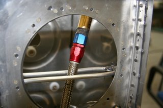
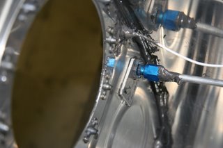
 I am installing the AFS AoA system. It is quite important to me since as I have mentioned elsewhere I fly in and out of a very short strip. It comprises two pressure sensors, one on the top of the wing and one on the bottom, together with a processor and display. The sensors need to be placed reasonably precisely, and surprisingly to me, are located in the final outboard bay of the RV4 wing. It makes for an easy installation. My surprise stems from the fact that the airflow at the tip can not be representative of the wing as a whole.
With the kit there is a #60 drill bit to drill the hole in the wing surface through which the pressure is sensed.
In this picture the sensors are not yet sealed in place. I will probably use proseal. The upper sensor has a sump with a drain valve in case water is sucked in. It seems unlikely through a #60 hole, though I suppose a descent in heavy rain might just force it in. I am told it very rarely does. On the ground you can operate the drain valve by means of a steel probe (supplied with the kit) through a hole you can just see in the top left hand corner of the picture, the bottom surface of the wing. To my surprise it is easy to find the drain valve with the rod without looking.
There is a nice touch with the kit. They suggest you use the blue tube (nearer the sky) for the upper sensor, and the green tube (grass) for the lower surface one.
Yes, I do jump around a bit in my work. I'll get back to the tips soon. Right now I am waiting on some welding.
Monday, September 04, 2006
Wing Tips
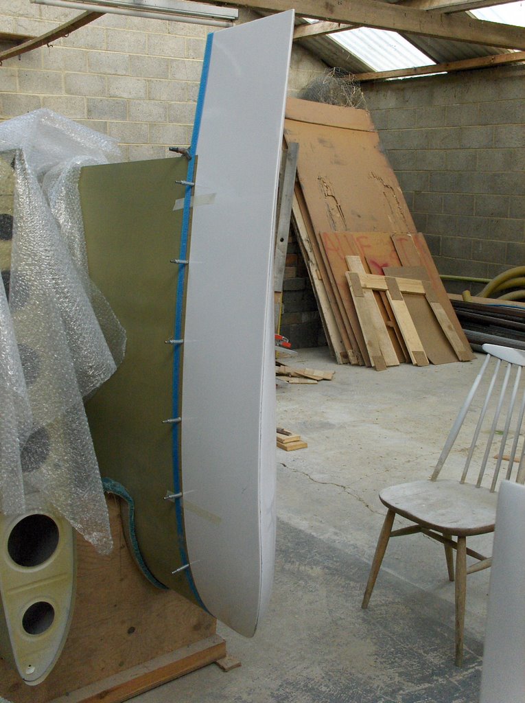 I have started on the left wing tip. Its well made, much better than the tips I received when I built an RV-9A. So far I have cut out a foam former which I have pressed inside the glass tip and pushed it onto the wing. I then used one of those straps (blue) with a ratchet to push the tip down to the leading edge. Without much pressure it pushed it about 1/8th inch forward against the leading edge. I am planning to make the tips removable with #6 screws and tinnerman washers at 2.5" spacing. For now I have marked out the hole locations and drilled every 3rd one with a #40 drill.
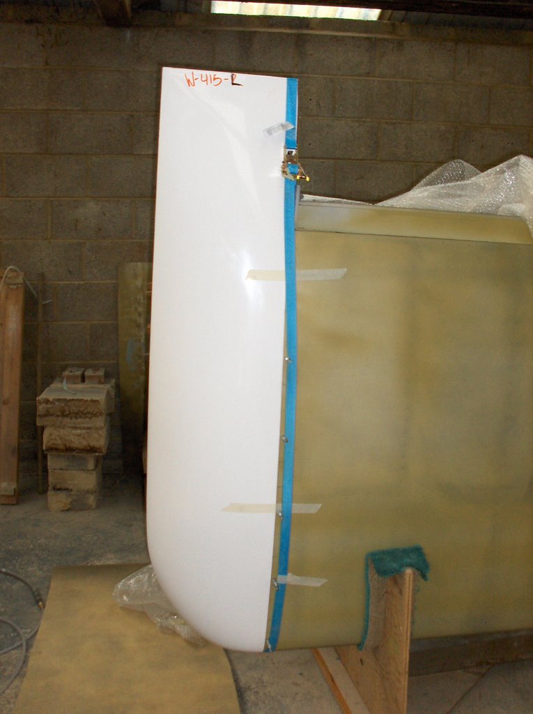 So far so good! I am worrying that I should have first locked the aileron in position to ensure alignment. I think I will do that next to be sure, though they are so stiff once mounted without attachment, that I doubt there will be much I can do to move where the trailing edge of the tip wants to sit. Lets hope it is in the right place!
I would strongly recommend having a foam mat on the floor when you are trying to get the tips on because they have a will of their own not wanting to go inside the wing.
Monday, May 29, 2006
Wings - fuel pick-ups
VANS issued SB 06-2-23, concerning the fuel pickups, just in time from my viewpoint, since work on the pickups had not started. Here in the UK building is controlled by the PFA and they were not concerned about strict adherence to the VANS methodology, though did want builders to be confident their tanks did not have a problem. Since at that stage I did not yet have a digital camera I had a friend take some pictures 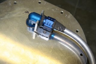 so that if ever in doubt, I could look back and say "yes they wont come undone". As you can see, I used Proseal. Well it holds everything else together so why not this?
This shows the right tank pickup.
The left tank pickup is a flop tube. In fact I am not building G-IKON for inverted flight, but it is one of those future proofing issues...just in case.
The final picture shows how the vent tube and capacitance signal line is terminated inside the tank.
 so that if ever in doubt, I could look back and say "yes they wont come undone". As you can see, I used Proseal. Well it holds everything else together so why not this?
This shows the right tank pickup.
The left tank pickup is a flop tube. In fact I am not building G-IKON for inverted flight, but it is one of those future proofing issues...just in case.

The final picture shows how the vent tube and capacitance signal line is terminated inside the tank.

![]()